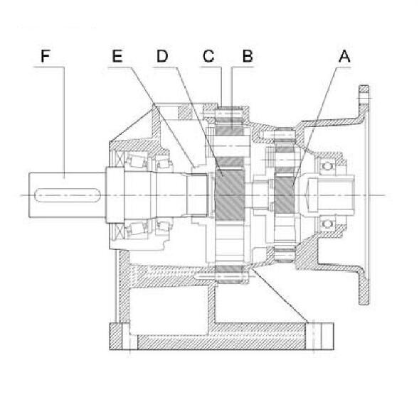
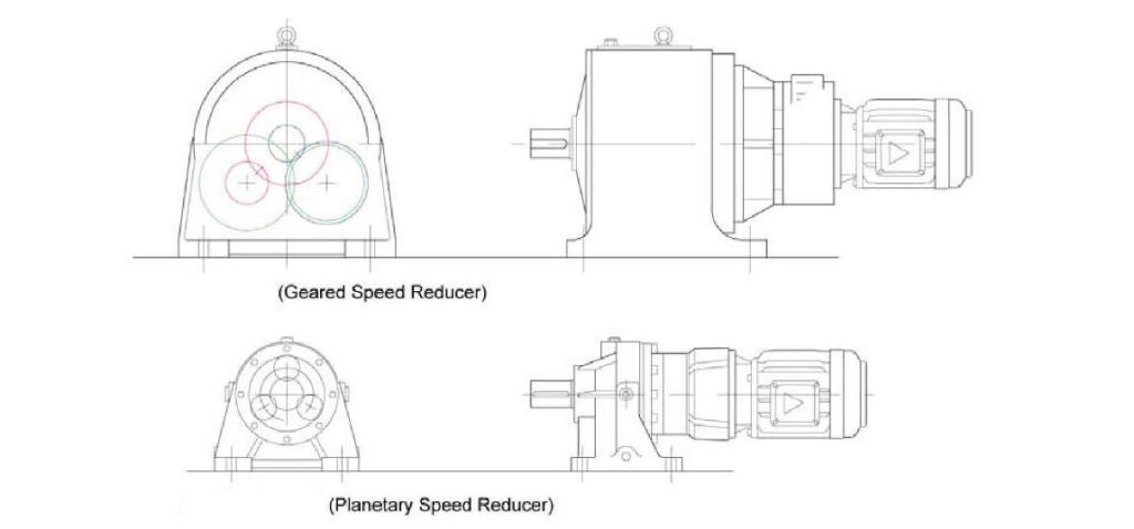
The transmission structure of the planetary speed reducer has the highest geared speed reducer efficiency among all the combinations. Its basic transmission structure includes:
- (A) Sun Gear
- (B) Planetary Gear (assembled with the planetary carrier)
- (C) Internal Gear Ring.
- (D)Staging Gear
The driving power through direct connection or link initiates the sun gear. The sun gear then drives the planetary gears assembled with the external gear ring to operate. The whole set of planetary gear systems revolves on its own axis and along the external gear ring, where the output shaft connected to the planetary carrier achieves the goal of speed reduction. A higher reduction ratio can be achieved by doubling the multiple staged gears and planetary gears.

| A | Sun Gear |
| B | Planetary Gear |
| C | Internal Gear Ring |
| D | Staging Gear |
| E | Planetary Carrier |
| F | Output Shaft |
Characteristics of Planetary Speed Reducer
High torque, impact resistance: The method of motion of a planetary gear structure is different from traditional parallel gears. Traditional gears rely on a small number of contact points between two gears to squeeze as the driving force, where all the loadings are concentrated on a few contacting surfaces, making it easy to wear and crack the gears, But the planetary speed reducer has six gear contacting surfaces with a larger area that can distribute the loading evenly over 360 degrees. Multiple gear surfaces share the instantaneous impact loading evenly which makes them more resistant to the impact from higher torques. The housing and bearing parts will not be damaged and crack due to high loading, either.
Small volume and lightweight: traditional design of geared speed reducers typically applies multiple sets of large and small gears to operate in a staggered pattern for power transmission and speed reduction. Because the reduction ratio needs to be generated by the multiples of tooth numbers of the two gears, there must be a certain engaging clearance between large and small gears. Therefore, the required space for the gearbox is relatively large. Especially for the combination of a high-speed reduction ratio, which needs a combination of more than two gearboxes and for which its structural strength will become relatively weak and enlarge its gearbox length, causing extremely large volume and weight. The structure of a planetary speed reducer can be designed for repeated connection according to the required number of stages and realizes the multiple staged combination alone. Its small volume, lightweight and compact outline make the equipment look more valuable.

High efficiency and low back clearance
Because there is only a single tooth surface engaged and contacted when each set of gears operates to reduce speed, the stress on the tooth surface should be larger when transmitting the same torque. Therefore, the gear design should apply a larger module and thickness. The larger the module is, the larger the deviation tolerance between gear teeth, which creates a relatively large gear clearance and increases the accumulated back clearance for each stage of speed reduction. The unique characteristic of uniform engagement of the planetary gear combination and arc enveloping structure of the external gear ring help with the robust engagement between the external gear ring and planetary gear. With the highly robust engagement between gears, apart from improving the extremely high-speed gear motors efficiency, the equipment itself can be selected to meet the requirements of positioning high precision.
ATO AC gear motor and DC geared motors have a large number of reduction ratios to choose from. The gear ratio of 75W-2kW DC planetary gear motors is up to 200, which meets the needs of most machines.